Hardware project · Electric Propulsion and Plasma Lab · Purdue CubeSat Lab
Payload Interface Board
Overview
I designed a compact sensor board for ground testing a pulsed electric thruster at Purdue. The thruster uses a brief electrical discharge through vaporized propellant, so testing needs to capture both the propellant supply conditions and the electrical behavior of each firing.
This board brings pressure, flow, and two types of current measurement into one STM32-based system. It gives the lab a single interface for connecting sensors to the test stand and reading them from a laptop. A removable Nucleo controller keeps development straightforward and lets me focus on the sensor circuits and PCB layout. The board is ground-test equipment; flight hardware is a separate development effort.
My contribution
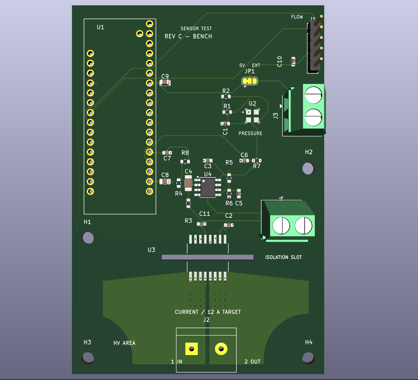
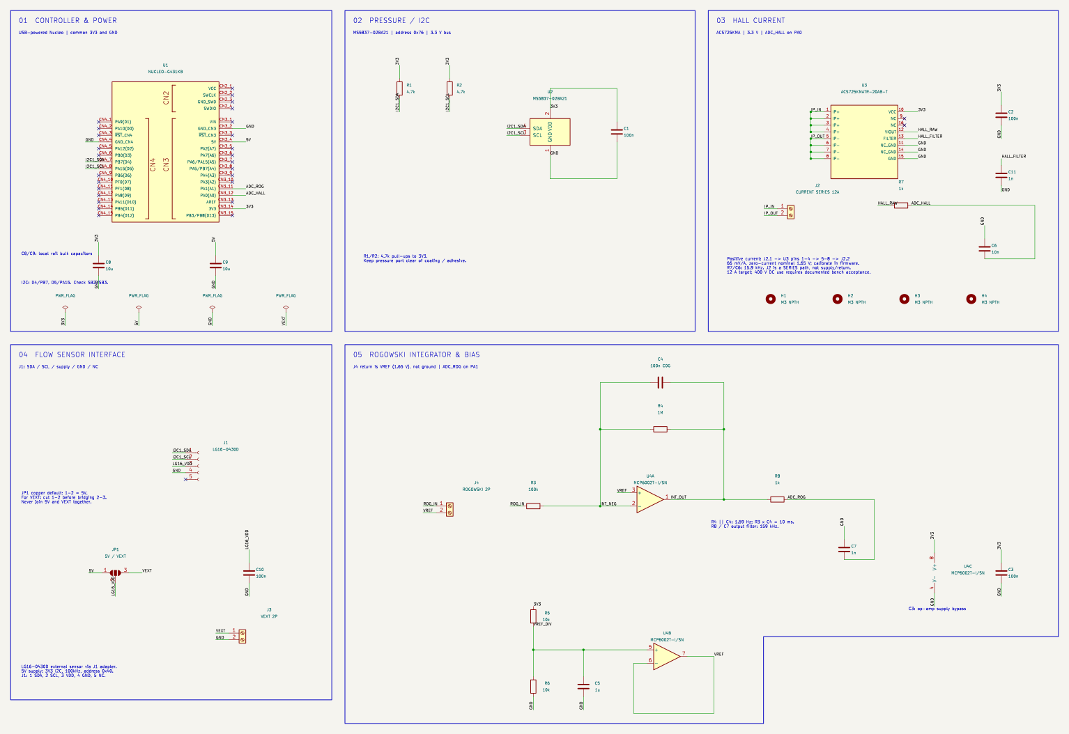
My work covers the schematic and PCB layout, from connecting the digital pressure and flow sensors to designing the analog circuits for the two current measurements. The main challenge is that those current channels are looking at very different things: one follows the payload's steady draw, while the other needs to capture a short discharge pulse.
I brought those circuits together on a 65 × 95 mm, two-layer board in KiCad, with a 12 A continuous-current design target. Keeping a removable Nucleo on top means I can use its existing power and programming connections and spend more time on the measurement side of the project.
Why these sensors
For pressure, I chose the MS5837 because our lab had already used it on FEMTA, an earlier project. That gave us a familiar starting point for getting the bench running. It does its own conversion and sends the reading digitally, so there is no extra amplifier to design for that channel.
The flow meter lives off the board, in the propellant feed line. We had gotten the Sensirion LG16 working at our revised flow target, so I gave it a connector on the board to bring its readings into the same system. I also made its supply selectable, leaving some flexibility if the sensor requirements change.
Current takes two different sensors. The ACS725 Hall sensor tells us how much current the payload is drawing while it runs. It reads the magnetic field around an internal conductor, which keeps the current being measured electrically separate from the microcontroller. That makes it useful for the slower, steady measurement, but it cannot tell us the shape of the discharge pulse itself.
That is where the Rogowski coil comes in. It loops around the discharge conductor without touching it electrically and responds to how quickly the current changes. To turn that signal back into a current waveform, I designed an integrating circuit on the board. The goal is to see the peak, ringing, and duration of each pulse; how well the circuit captures those details still needs to be checked on the bench, particularly the amplifier's bandwidth.
Project status
Schematic and PCB layout complete. Bench validation is planned after the Critical Design Review; measurement accuracy and current-handling performance still need to be verified.