Hardware project · Purdue CubeSat Lab
Accumulator PCB
Overview
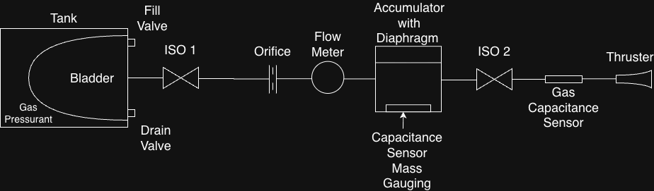
The accumulator is a component in the UNP-sponsored apexsat project that uses the AFRL's ASCENT propellant.
The accumulator collects ASCENT propellant at the set mass flow rate of 8g/us inside an expanding bladder. A conductive plate attached beneath the bladder moves toward a second plate on the housing floor as it fills. I designed this such that measuring the capacitance between them provides a way to infer bladder motion and, with a calibrated geometry, the accumulated volume of propellant.
This compact PCB reads that capacitance with an FDC1004 and sends measurements over I²C to an STM32 Nucleo. Revision A places the sensing connection and driven shield beside the converter, with a separate 3.3 V host connection.
PCB views
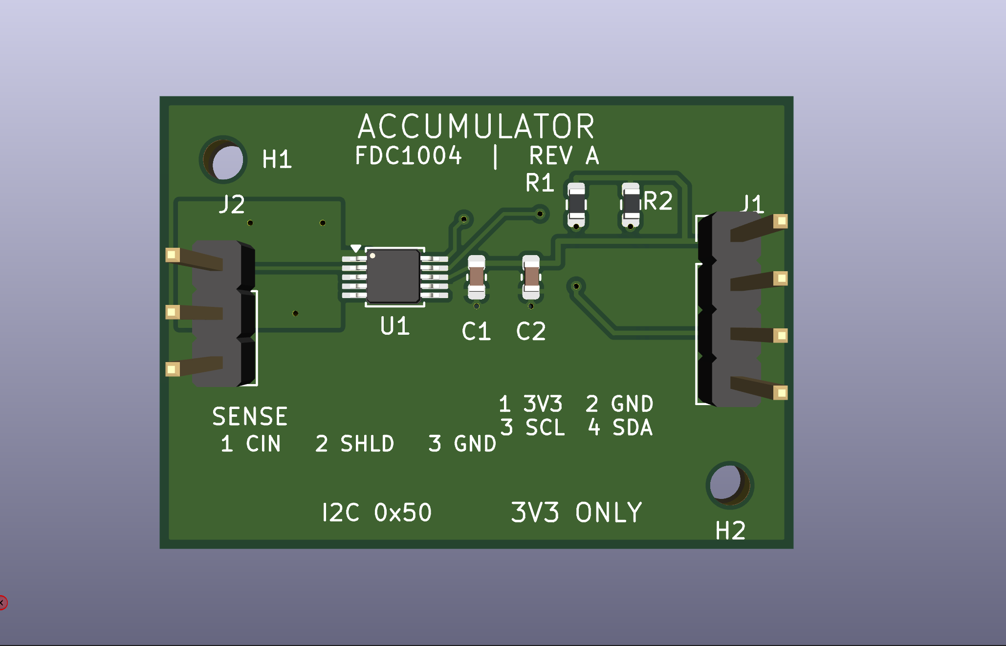
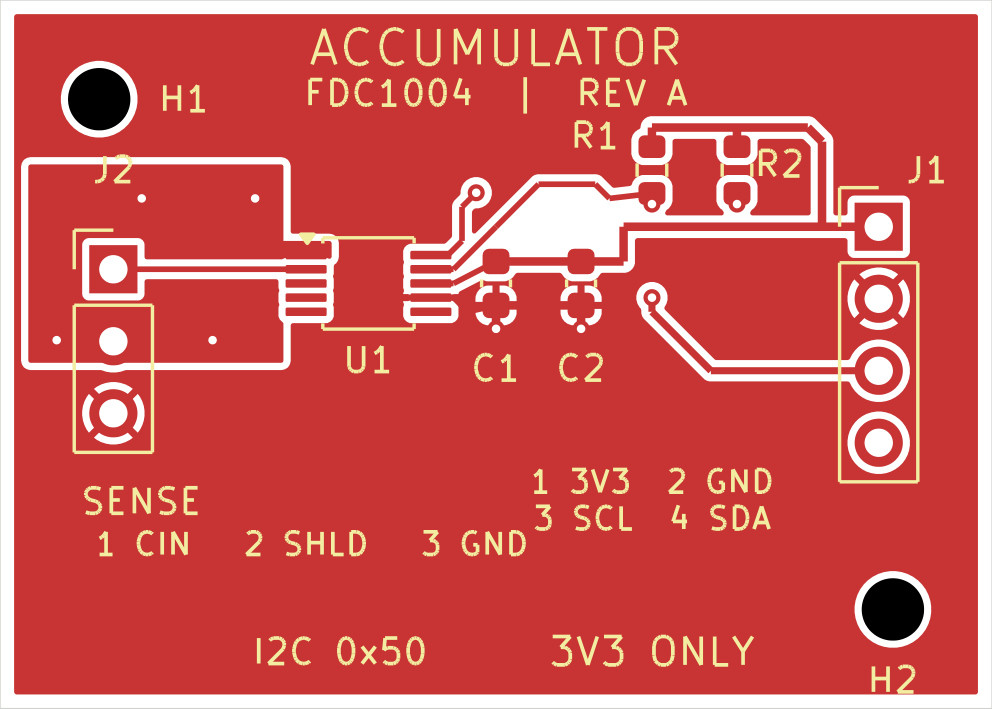
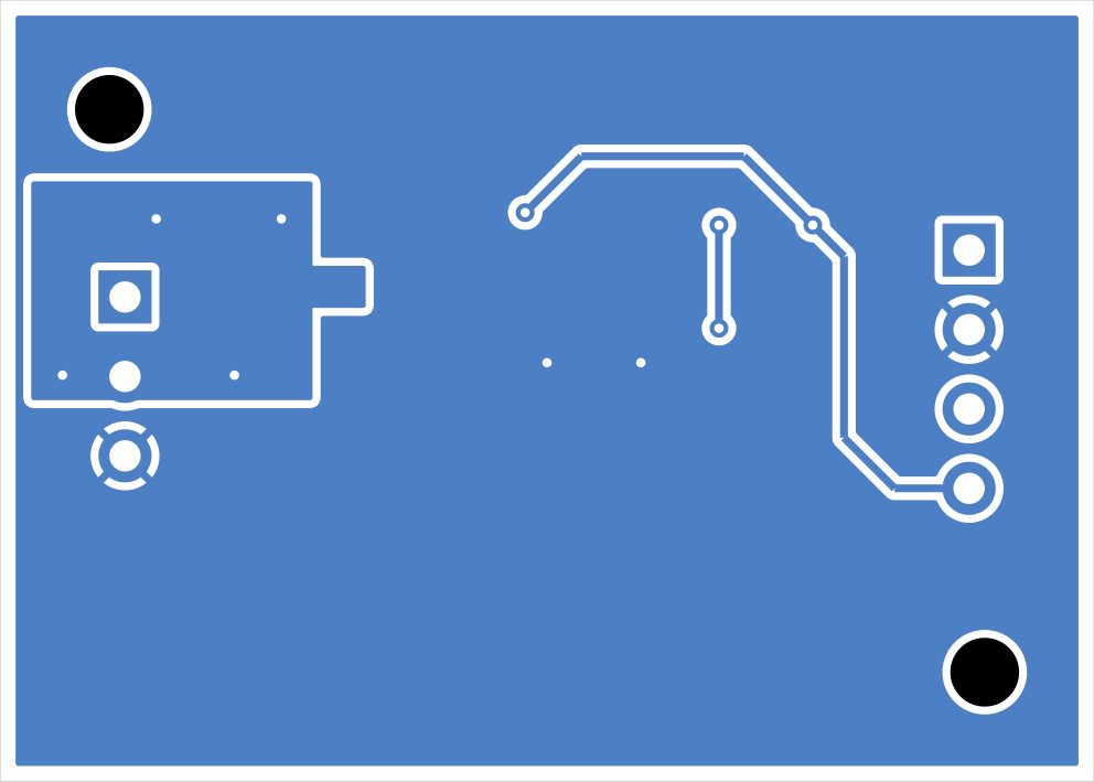
But... why?
In the development of our pulsed-magnetoplasma dynamic thruster, henceforth known as the PMPD, we encountered an issue with our ability to calculate our specific impulse. Understood colloquially as the efficiency of a given thruster, the Isp requires an accurate mass flow rate to be calculated. This is a parameter to keep track of with the PMPD, because it is a novel thruster and thus we need to prove, through experimental measurements, that we are making genuine improvements over existing pulsed plasma thrusters.
The solution to this problem is the Accumulator, which accumulates mass that it measures with its internal diaphragm, and records mass over time with a lower required mass flow rate than the market-available coriolis flow meters.
The mechanism
The proposed rigid backing beneath the bladder helps the moving electrode stay flat. Keeping the plates parallel makes the electrical measurement easier to relate to displacement; the mechanical design must also maintain clearance throughout the fill cycle.
Accumulator CAD
Interactive 3DLoading accumulator model…
Mathematical model
The accumulator was based on a parallel-plate capacitance model: bladder motion changes the plate gap, and that change provides an estimate of stored propellant volume.
Capacitance → displacement → volume
Relate capacitance to the gap
As the bladder pushes the moving plate toward the fixed plate, the gap decreases and capacitance increases.
Recover plate displacement
Use the empty accumulator as the reference. A positive displacement corresponds to the plates moving closer together.
Estimate the volume change
For a constant effective swept area, volume change is area × displacement. This idealized extension of the gap model must be calibrated to the actual bladder geometry.
- C / Cempty
- Plate capacitance / empty reference
- A
- Overlapping electrode area
- d / Δh
- Plate gap / displacement from empty
- Aeff
- Effective swept area of the bladder
- ε₀
- 8.854 × 10⁻¹² F/m, for an approximately air-filled gap
- ΔV
- Volume change relative to empty
PDR presentation
Slides coming soon